
Installation & Wiring
What you’ll need
Section titled “What you’ll need”- Marigold-5 module
- Wire strippers & cutters
- 16-18 AWG red and black wire
- 15-20A circuit breaker for the PDH
- USB-C cable rated for at least 3A
- #6-32 mounting hardware or zip ties
Mounting
Section titled “Mounting”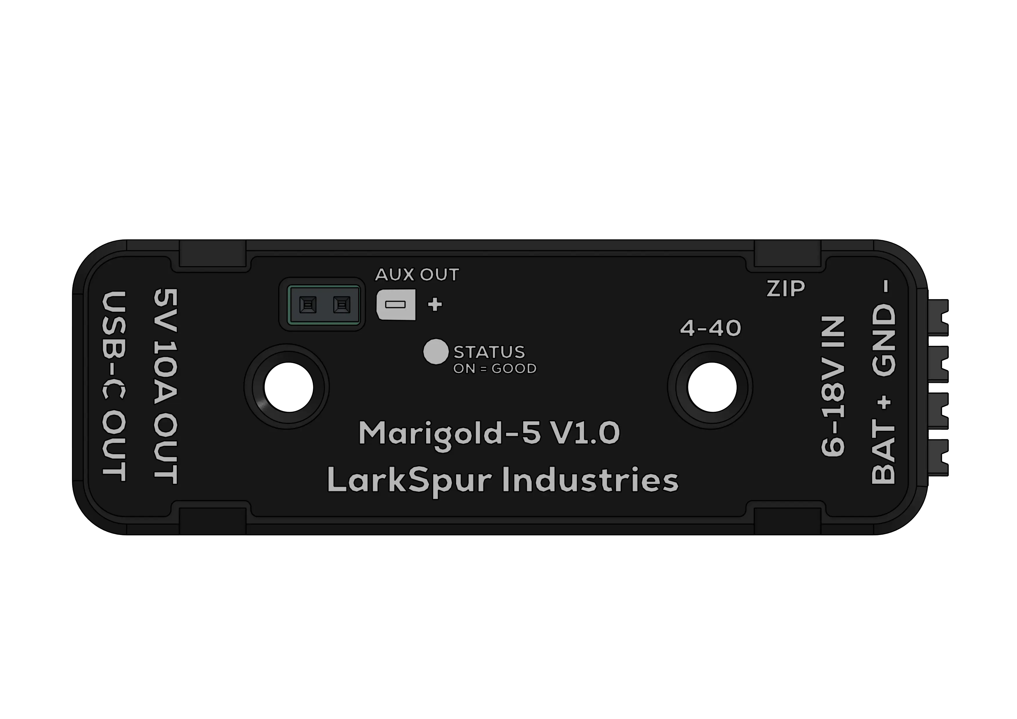 Top view showing mounting points
Bolt mounting
Section titled “Bolt mounting”- Recommended for optimal heatsinking.
- Use the two #6-32 holes with 1.25-inch center spacing.
Zip-tie mounting
Section titled “Zip-tie mounting”- Route zip ties on the four points around the case perimeter.
- Inspect the ties regularly because they can loosen over time.
Wiring input power
Section titled “Wiring input power”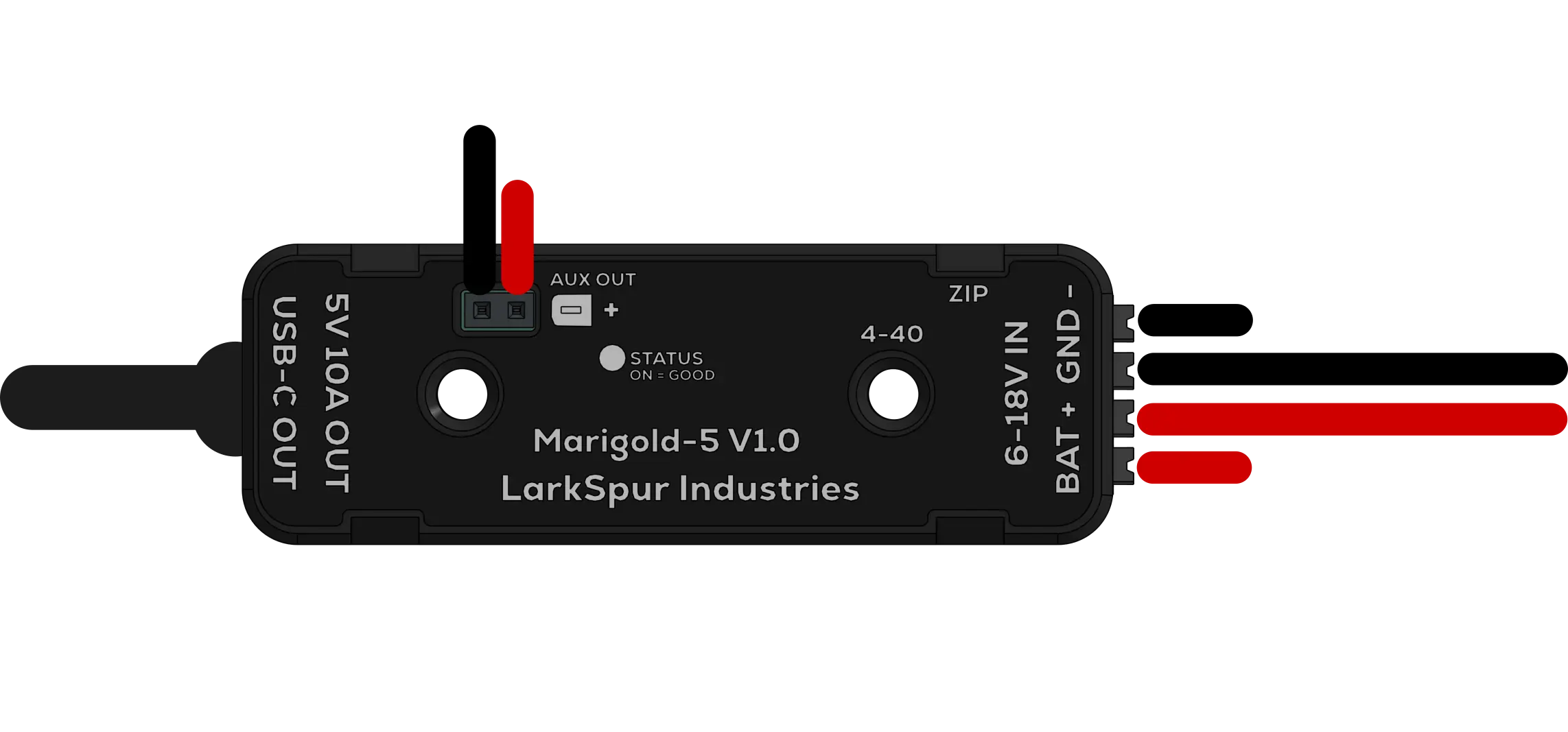 Marigold-5 wiring diagram
| Parameter | Value |
|---|---|
| Wire gauge | 16-24 AWG |
| Strip length | 7-8 mm |
The input terminal block accepts 16-24 AWG wire. When using the recommended 15-20A branch-circuit breaker, use 16-18 AWG copper wire. Smaller wire may fit the connector but is not recommended.
The terminal block has four positions: two tied to BATT+ and two tied to GND. The pins in each pair are internally connected, so a single input pair is enough for normal use. The spare pair is there for daisy-chaining or for splitting the input across two conductors.
| Pin | Function | Wire color |
|---|---|---|
| BATT+ (×2) | +12V input | Red |
| GND (×2) | Ground | Black |
Wiring procedure
Section titled “Wiring procedure”- Remove exactly 7-8 mm of insulation. A shorter length may prevent a secure connection, while a longer length leaves exposed conductor.
- Press the white push button on the terminal block. You may have to use a small screwdriver.
- Fully insert the red wire into BATT+ and the black wire into GND.
- Release the button so the spring clamp secures the wire.
- Gently tug each wire to verify that it is secure.
- Install your 15-20A breaker in the PDH port before connecting battery power.
Connecting devices
Section titled “Connecting devices”USB-C output
Section titled “USB-C output”- Role: Source (DFP)
- Advertised current: 3A through 10 kΩ CC pull-ups
- USB Power Delivery: Not supported
While the USB-C port advertises 3A, many devices, such as co-processors, consume more. Make sure to connect a cable rated for at least 3A. If using the locking cable, tighten its retention screw. Thin or low-quality cables can cause excessive voltage drop.
| Device | Typical current draw |
|---|---|
| Raspberry Pi 4/5 | 2-4A |
| Orange Pi 5 | 2-5A |
| Arduino/ESP32 | 0.2-0.5A |
| LED strips | Varies; often 2-5A |
Co-processor wiring diagrams
Section titled “Co-processor wiring diagrams”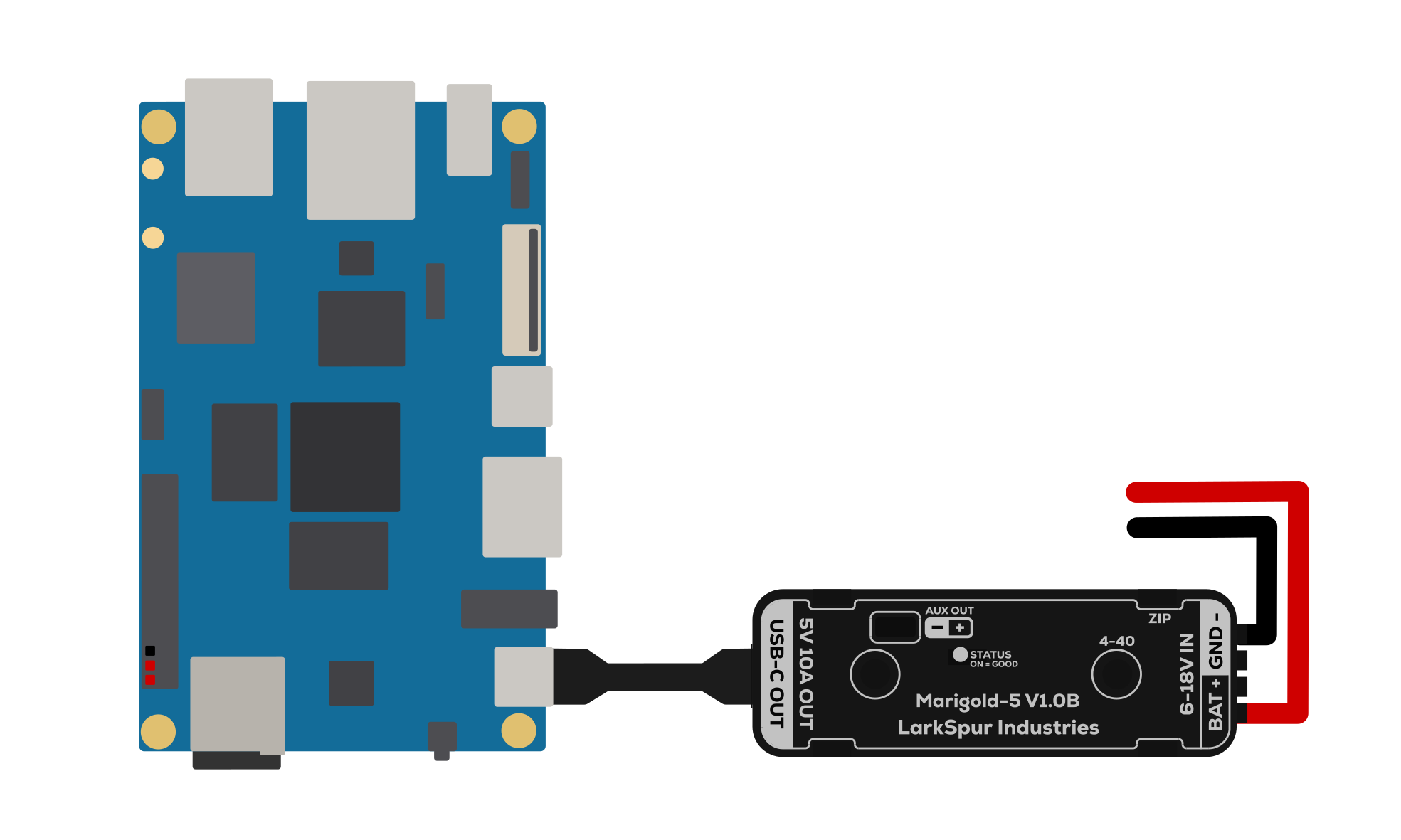 Orange Pi 5B wiring diagram
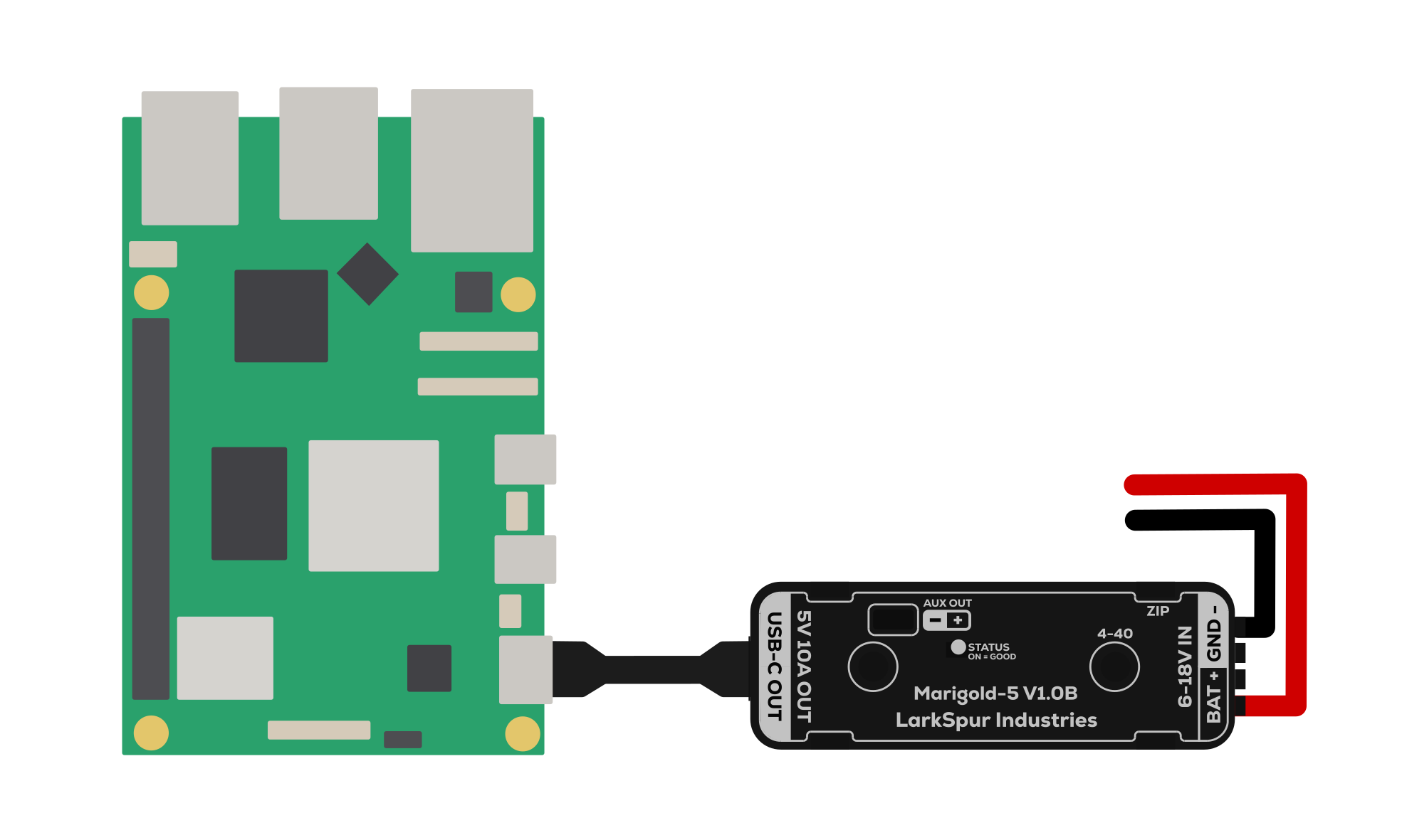 Raspberry Pi 5 wiring diagram
Auxiliary output
Section titled “Auxiliary output”The auxiliary output uses a pin header with a 2.54 mm pitch.
| Pin | Function |
|---|---|
| + | 5.1V output |
| − | Ground |
The auxiliary output can power cooling fans, indicator LEDs, microcontrollers, and compatible 5V network equipment. Its load counts toward the combined output current. The recommended combined load is 5-6A for continuous operation, with a 7A continuous maximum. Limit 8-10A loads to a few seconds unless adequate user-supplied active heatsinking and cooling are installed.
Power on and verify
Section titled “Power on and verify”- Turn on the robot’s main power.
- Confirm that the STATUS LED is solid orange.
- Confirm that the connected co-processor boots normally.
- Optionally measure 5.1V ± 0.1V at the auxiliary output with a multimeter.
If the STATUS LED remains off, continue to troubleshooting.