Marigold-5 Documentation
1. Device Overview
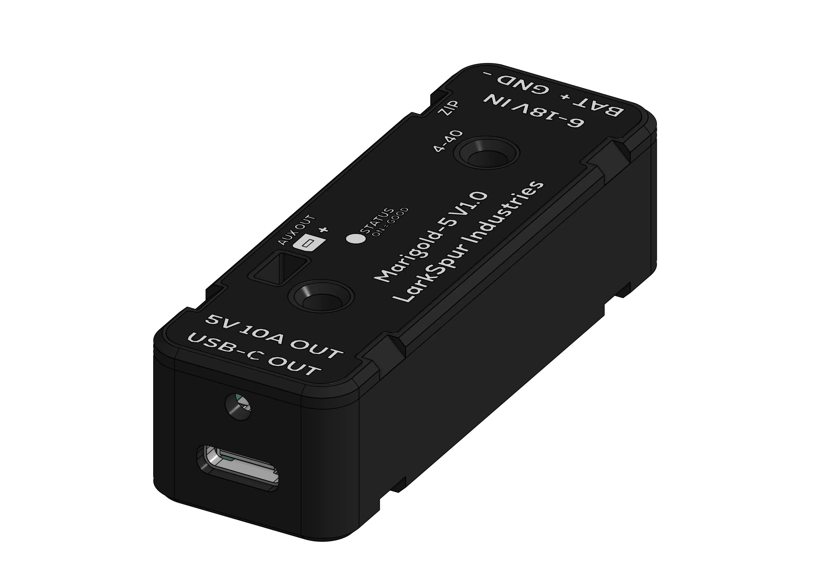 Figure 1.1: Marigold-5 Corner View
The Marigold-5 is a synchronous step-down (buck) DC-DC converter module designed to provide a regulated 5.1V rail for FIRST Robotics Competition applications. It accepts a wide input voltage range (6V–18V) suitable for FRC lead-acid battery architecture and distributes power via a single high-current USB-C receptacle and one auxiliary output.
Built around the Texas Instruments TPS56A37, the Marigold-5 solves the common challenge of reliably powering co-processors (Raspberry Pi, Orange Pi) and other devices like network equipment with robust, high-current 5.1V power and secure mounting options.
2. Key Features
- High-Current USB-C Port: Rated for 3A continuous per port, 10A system total
- Type-C Current Advertisement: Uses standard 10 kΩ CC pull-up resistors to advertise 3A capability to non-PD sink devices
- Brownout Protection: Maintains stable 5.1V output down to 6V input, keeps your co-processor running during battery voltage sags
- Secure Mounting: Bolts directly to 1×2" aluminum extrusion using standard #4-40 hardware with 1.25" spacing, or use integrated zip tie points
- Built-In Protection: Reverse polarity (PMOS), input TVS diode (voltage spikes), thermal shutdown (165°C), and overcurrent limiting
3. Safety & Warnings
- Do not exceed 18V input voltage - Maximum rated input is 18V DC
- Do not exceed 10A total output current - Combined load across USB-C and auxiliary output
- Do not reverse polarity - Red wire to BATT+, black wire to GND only
- Keep away from conductive debris - Metal shavings, water, or tools can cause short circuits
- Ensure adequate airflow - Device may reach high temperatures under sustained 10A loads
FRC Compliance:
This device is designed for FIRST Robotics Competition use and complies with FRC power distribution rules. Always verify current game manual rules before competition.
4. Installation & Setup
4.1 What You'll Need
- Marigold-5 module
- 16-22 AWG wire (red and black)
- Wire strippers
- 15-20A circuit breaker (for PDH)
- USB-C cable rated for 3A
- Mounting hardware (#4-40 screws or zip ties)
4.2 Mounting
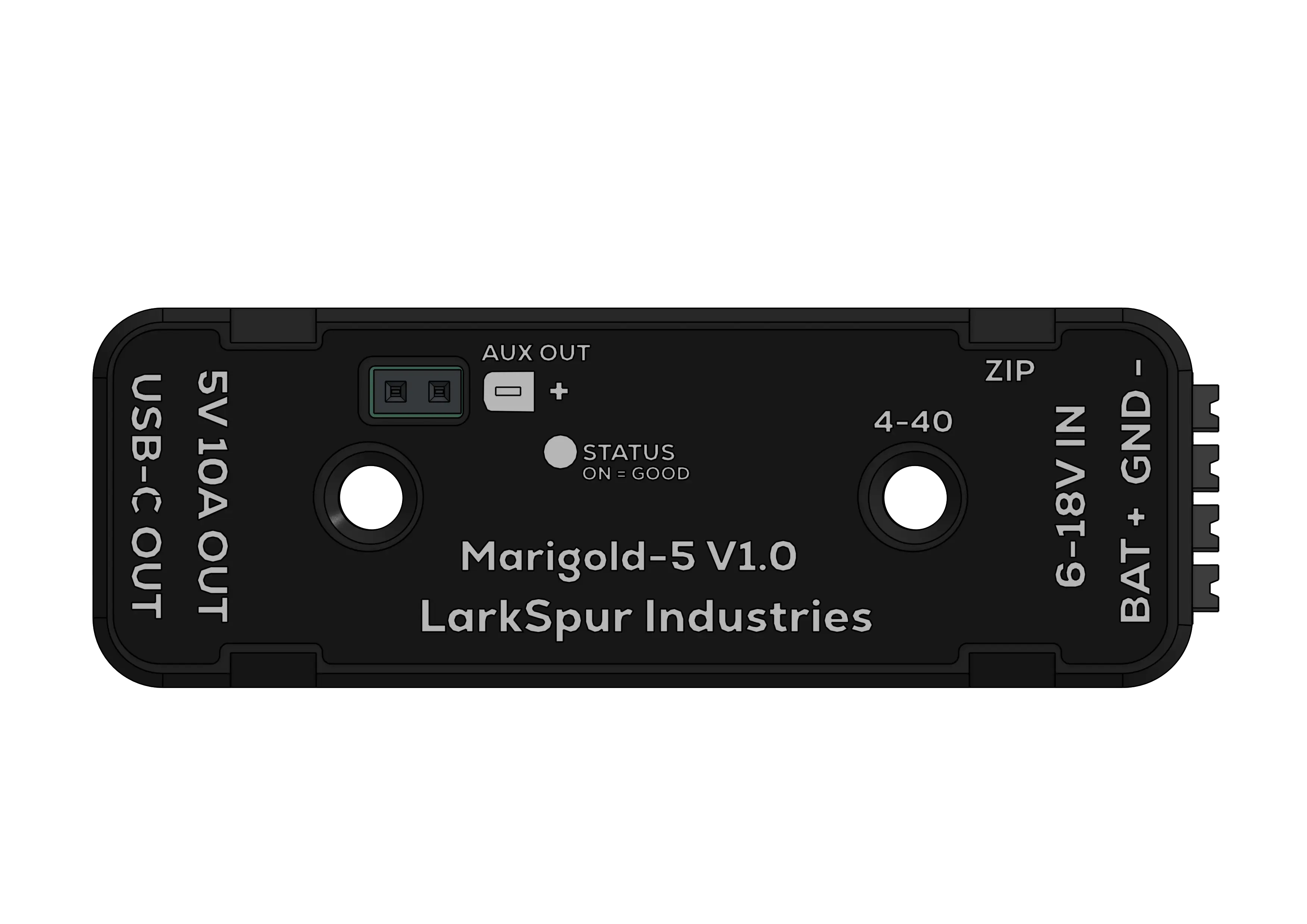 Figure 4.1: Top View Showing Mounting Points
Option 1: Screw Mounting (Recommended)
- Two #4-40 threaded inserts with 1.25" spacing
- Compatible with standard 1×2" FRC aluminum extrusion
- Use #4-40 screws up to 0.5" length
Option 2: Zip Tie Mounting
- Four integrated zip tie points on case perimeter
- Quick installation
- May become loose over time
4.3 Wiring Input Power
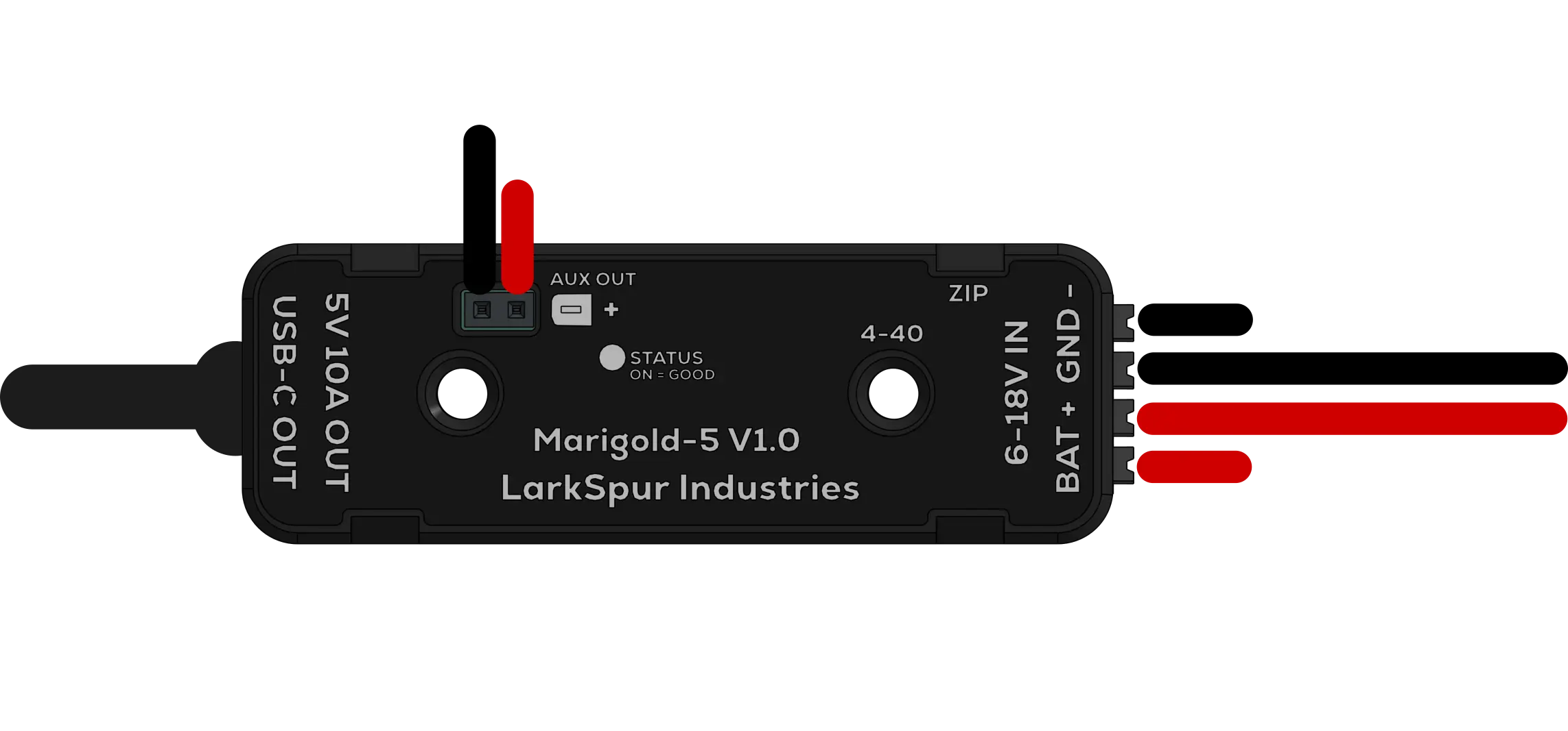 Figure 4.2: Wiring Diagram
Input Connector: TBLH10-350-04BK Spring Cage Terminal Block
Specifications:
| Parameter | Value |
|---|---|
| Rated Current | 10A (UL), 17.5A (IEC) per contact |
| Wire Gauge | 16-24 AWG (0.2–1.5mm²) |
| Strip Length | 7-8mm |
Pinout:
| Pin | Function | Wire Color |
|---|---|---|
| BATT+ | +12V Input | Red |
| BATT+ | +12V Input | Red |
| GND | Ground | Black |
| GND | Ground | Black |
How to Wire:
- Strip exactly 7–8mm of insulation, too short and the wire won't make contact, too long creates a fragile connection
- Press the white push button on the terminal block
- Insert red wire into BATT+, black wire into GND, push fully until the wire bottoms out
- Release the button, the spring clamp automatically secures the wire
- Tug-test both wires to confirm they are seated
- Install a 15–20A breaker in your PDH port before connecting to the battery
4.4 Connecting Your Devices
USB-C Output Port
- Role: Source (DFP)
- Advertised Current: 3A (Legacy, via 10 kΩ CC pull-up)
- USB-PD: Not supported
Plug your USB-C cable into the Marigold-5 port and the other end into your co-processor. If using a locking cable, secure the retention screw.
| Device | Typical Current Draw |
|---|---|
| Raspberry Pi 4/5 | 2–4A |
| Orange Pi 5 | 2–5A |
| Arduino/ESP32 | 0.2–0.5A |
| LED Strips | Varies (check specs) |
Use cables rated for 3A minimum. Thin or low-quality cables cause voltage drop, our locking USB-C cable is recommended for robot or high vibration use.
Co-Processor Wiring Diagrams
 Figure 4.3: Orange Pi 5B Wiring Diagram
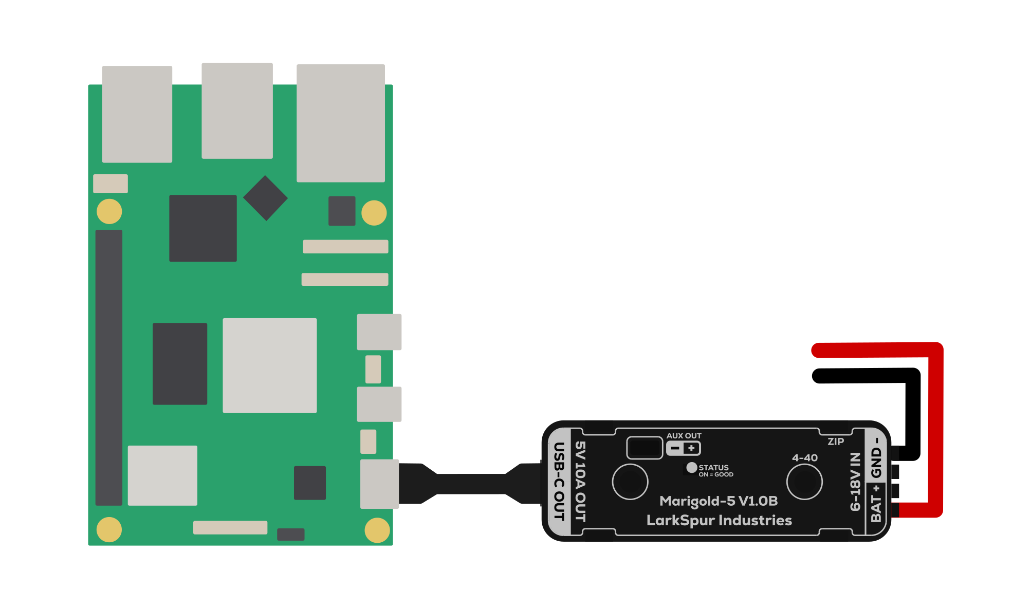 Figure 4.4: Raspberry Pi 5 Wiring Diagram
Auxiliary Output Header
Connector: 2.54mm pitch pin header
| Pin | Function |
|---|---|
| (+) | 5.1V Output |
| (-) | Ground |
Suitable for cooling fans, LED indicators, Arduino/microcontroller power, and 5V network switches. The auxiliary output shares the 10A total system limit with the USB-C port (e.g., if USB-C draws 3A, the auxiliary header has 7A available).
4.5 Power On & Verify
- Turn on robot main power
- Confirm the STATUS LED is orange (solid), this indicates stable 5.1V output
- Check that your co-processor boots normally
- Optionally, measure 5.1V ± 0.1V at the auxiliary output pins with a multimeter
If the STATUS LED is off, see the Troubleshooting section.
6. Understanding the Output Voltage
Why 5.1V Instead of 5.0V?
The 5.1V output is intentional and by design. Here's why:
The Problem:
USB cables, especially longer or lower-quality ones, introduce resistance (typically 0.1–0.5Ω per meter). At 3A load, Ohm's Law tells us:
- Voltage drop = Current × Resistance
- At 3A through 0.3Ω cable: 0.9V drop
The Solution:
Starting at 5.1V ensures the device at the end of the cable receives ≥4.75V (the USB minimum spec), even under full load with imperfect cables.
Industry Practice:
High-quality USB power supplies output 5.1V-5.2V for exactly this reason. It's standard practice in industrial and embedded applications.
7. LED Status Indicator
STATUS LED Behavior
Located on top of the case, the STATUS LED provides real-time feedback on device operation.
| LED State | Meaning | Action Required |
|---|---|---|
| 🟠 Orange (Solid) | Normal operation - output is stable at 5.1V | None |
| ⚫ Off | Fault condition detected | See troubleshooting below |
What Causes the LED to Turn Off?
The STATUS LED is driven by the TPS56A37's integrated Power Good (PG) function. It turns off when:
- Input power disconnected - Check PDH breaker and wiring
- Reverse polarity detected - Swap red and black wires
- Output voltage out of range - Load draws >10A or output is shorted
- Thermal shutdown - Junction temperature >165°C (improve airflow)
- Undervoltage lockout - Input voltage <4.2V (battery critically low)
The PG circuit includes built-in deglitch timing to prevent false triggers from transients.
8. Troubleshooting
Device Not Powering On (STATUS LED Off)
Check input voltage:
- Measure voltage at terminal block: should be 6-18V
- If below 6V: Battery is critically discharged or wiring has high resistance
- If above 18V: Disconnect immediately - input overvoltage
Verify polarity:
- Red wire should be on BATT+
- Black wire should be on GND
- If reversed, the PMOS protection prevents damage, but device won't operate
Inspect wiring:
- Ensure wires are fully inserted into terminal block
- Check for corrosion or loose connections at PDH
- Verify breaker is not tripped (reset if necessary)
Try power cycle:
- Disconnect input power for 30 seconds
- Reconnect and observe STATUS LED
USB Devices Not Booting or Charging
Cable quality issues:
- Try a different USB-C cable rated for 3A
- Measure voltage at device end: should be >4.75V under load
- Long or thin cables create excessive voltage drop
Current limit exceeded:
- Check total load: USB-C + auxiliary output must be <10A combined
- Some devices have inrush current spikes at boot (normal, usually brief)
Device compatibility:
- Verify your device accepts 5V input (not 9V, 12V, or 20V PD)
- Some devices require USB-PD negotiation and will not charge from this module
Overheating (Device Feels Very Hot)
This is usually normal behavior:
- The Marigold-5 is designed to operate at high temperatures
- At 10A load, the regulator and MOSFETs generate significant heat
- Case acts as heatsink to dissipate this heat to ambient air
When to take action:
- If STATUS LED turns off → Thermal shutdown activated (>165°C)
- If device becomes too hot to touch for >2 seconds → Improve airflow
Solutions:
- Reduce total load current to <8A
- Mount device in location with better airflow
- Add small 5V fan (powered from auxiliary output) to blow air across case
- Avoid mounting in enclosed boxes without ventilation
Understanding FRC Brownouts
What is a brownout?
During high-current maneuvers (hard acceleration, pushing matches, climbing), the robot battery voltage can sag from 12V down to 6-7V for several seconds. This is normal FRC battery behavior due to internal resistance.
Why does this matter for co-processors?
Most generic 12V→5V USB adapters (car chargers, Amazon specials) have a minimum input voltage of 9-10V. When battery voltage drops below this threshold during a brownout, the adapter shuts down, causing your:
- Raspberry Pi to reboot (losing AprilTag tracking mid-match)
- Vision processing to restart (missing critical auto routines)
- NetworkTables to disconnect (breaking driver feedback)
How Marigold-5 solves this:
The TPS56A37 buck converter is designed for 6V minimum input. During a match when your battery sags to 6-7V, Marigold-5 continues providing stable 5.1V output, keeping your co-processor running without interruption.
9. Downloads & Resources
Documentation
Wiring Diagram (PNG)
Case Drawing (PDF)
3D Models
10. Technical Specifications
10.1 Electrical Characteristics
| Parameter | Minimum | Typical | Maximum | Units |
|---|---|---|---|---|
| Input Voltage | 6.0 | 12.0 | 18.0 | V DC |
| Input Surge Voltage | - | - | 22 | V DC |
| Output Voltage | 5.00 | 5.10 | 5.20 | V DC |
| Output Voltage Accuracy | - | ±2% | - | - |
| Continuous Output Current | - | - | 10 | A |
| Peak Output Current | - | - | 12 | A (brief) |
| Switching Frequency | - | 500 | - | kHz |
| Quiescent Current | - | 45 | - | µA |
| Shutdown Current | - | 3 | - | µA |
| Efficiency @ 5A, 12Vin | - | ~90% | - | % |
10.2 Protection Features
| Protection | Threshold | Response |
|---|---|---|
| Reverse Polarity | Any | PMOS blocks current, no damage |
| Input Overvoltage | >22V | TVS diode clamps, may damage if sustained |
| Output Overcurrent | >10A (valley) | Cycle-by-cycle current limiting |
| Output Overvoltage | >125% of target | Shutdown after 32µs deglitch |
| Output Undervoltage | <65% of target | Hiccup mode restart after 256µs |
| Thermal Shutdown | >165°C junction | Automatic shutdown, auto-restart at 135°C |
| Input UVLO | <4.2V rising | Device disabled until Vin >4.2V |
10.3 USB-C Port Configuration
| Parameter | Value |
|---|---|
| Port Role | Source (DFP) |
| CC Resistor Configuration | 10 kΩ to VBUS (both CC1 and CC2) |
| Advertised Current | 3A (per USB Type-C spec) |
| Data Lines (D+/D-) | Floating (no data communication) |
| USB-PD Support | No (fixed 5.1V output only) |
10.4 Mechanical Specifications
| Parameter | Specification |
|---|---|
| Dimensions (L × W × H) | 2.52" × 0.87" × 0.67" (64mm × 22mm × 17mm) |
| Weight | ~45g |
| Case Material | PETG (Black) |
| Mounting Hole Pattern | Two #4-40 threaded inserts, 1.25" spacing |
| Mounting Screw Length | 0.5" maximum |
| Operating Temperature | -40°C to +60°C ambient (derated above 50°C) |
| Storage Temperature | -40°C to +85°C |
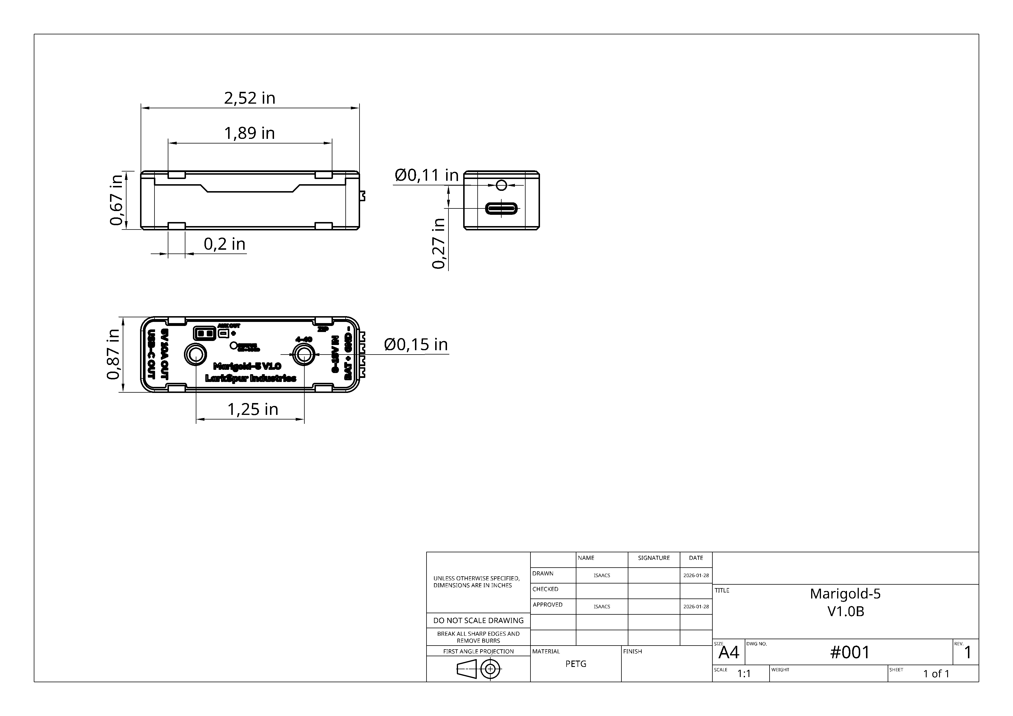 Figure 10.1: Mechanical Drawing with Dimensions
11. Warranty & Support
Warranty Information
Larkspur Industries provides a warranty on the Marigold-5.
For complete warranty terms and RMA process, see our Warranty Policy.
Contact Information
For technical support, sales inquiries, or feedback:
- General Support: [email protected]
- Sales & Quotes: [email protected]
- Engineering Questions: [email protected]
Community Resources
- GitHub: github.com/LarkSpur-Industries
Document Revision: V1.2
Last Updated: February 3, 2026
© 2026 Larkspur Industries